How WII5 buoys talk — Iridium for over-the-horizon, local channels for in-the-field configuration.
WII5 buoys use two communication channels — long-range satellite for
operational telemetry, and short-range local for field configuration and
read-out without breaking the enclosure seal.
Local — BLE, serial, and Wi-Fi for in-field access.
1.1 - Iridium
Over-the-horizon satellite uplink using Iridium short-burst-data.
Iridium short-burst-data is the primary operational channel: small payloads,
global coverage, low power per message. Each transmission carries a
calculated wave-statistics packet rather than raw samples.
Status: placeholder.
1.2 - Local
In-field local channels — BLE, serial, and Wi-Fi for configuration and read-out.
Local channels used in-field for configuration, diagnostics, and read-out
without breaking the enclosure seal: BLE for app-driven access, serial for
direct console, and Wi-Fi for higher-bandwidth bulk download.
Status: placeholder.
2 - Calculations
On-board calculations — wave statistics and directional analysis.
What the buoy turns its raw sensor stream into before transmission.
The wave-statistics calculation reduces raw accelerometer samples to a
compact summary: significant wave height (Hs), peak period (Tp), and total
wave energy across the spectrum.
Status: placeholder.
2.2 - Direction
Directional wave-spectrum analysis from accelerometer + GPS heading.
Directional analysis combines accelerometer data with GPS heading to
estimate where the wave energy is coming from.
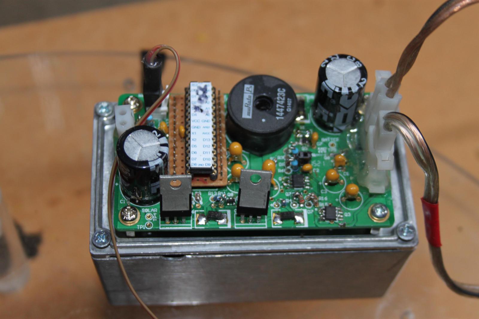
Solar charging via MPPT — maximum power point tracking. Custom-designed for the small batteries used in solar WII buoys, because nothing off-the-shelf fit.
MPPT (maximum power point tracking) charge controller for the solar input
that keeps the battery pack alive between sunny windows.
Why we designed our own
At the small battery sizes used in solar WII buoys, no off-the-shelf
MPPT existed that was a good fit — commercial MPPT controllers were
designed back then for vehicle, off-grid, or marine packs at least an order of
magnitude larger than what a buoy carries. The available options were
either too lossy at low currents, drew too much quiescent power, or had
input/output ranges that didn’t match a small solar panel + lithium-pack
combination.
So we built our own. The result is an MPPT optimised for:
Small battery capacity — sized for the buoy pack, not a vehicle.
Low quiescent draw — the controller itself can’t be a meaningful
fraction of the buoy’s deep-sleep current budget.
Small panel — input range matches the panels we can fit on a
buoy enclosure top, with anti-slide spikes and antenna clearance
around them.
Cold operation — has to keep working at the Antarctic temperature
range, where commercial controllers often spec out.
Status: placeholder. Schematic, board layout, efficiency curves, and
deep-sleep current measurements to follow.
3.2 - GPS
GPS — position, time, and directional heading.
GPS provides position, timing, and where supported, directional heading used
in the directional wave-spectrum analysis.
Status: placeholder.
3.3 - Kistler
Kistler high-precision accelerometer for wave-motion measurement.
Kistler high-precision accelerometer. Used where the IMU’s MEMS
accelerometer doesn’t have enough resolution for the wave-motion
calculations.
Status: placeholder.
3.4 - IMU
Inertial measurement unit — accelerometer, gyroscope, magnetometer.
The IMU provides 9-axis motion data: accelerometer, gyroscope, and
magnetometer, used for orientation and motion estimation alongside the
Kistler.
Status: placeholder.
3.5 - Temperature
Water and internal temperature sensing.
Temperature sensors for water (where the buoy enclosure permits) and
internal electronics monitoring.
Status: placeholder.
3.6 - Anemometer
Wind speed and direction sensor.
Anemometer for wind speed and direction. Carried on variants intended for
combined sea-state and atmospheric observation.
Status: placeholder.
3.7 - Cameras
Visual deployment and surface-imaging cameras.
Cameras carried by some variants for visual deployment confirmation and
surface imaging during operation.