WII5 wave buoys — every type from WII1 through WII5, the AVR firmware that runs them, electronic schematics, enclosures, and the tools used to configure them.
The physical buoy and everything that lives on it: the firmware, the main
board, the enclosure, and the field tools used to configure and read it.
Types — WII1 through WII5, with sub-types for the WII4 (Edison-era) and WII5 (AVR-era) variants.
Firmware — AVR/ESP32 control code (the heart of the current release).
Onboard data processing — the on-buoy maths (Alison Kohout’s wave-motion algorithms) that reduces raw acceleration into the wave-statistics payload before transmission. Lives under Software → Onboard Data Processing.
Test Equipment — static wave/heave tester, off-grid access points, local real-time dashboards, and BLE / Wi-Fi access boxes.
1 - Firmware
AVR/ESP32 control firmware — the C++ code that runs on every WII5 buoy.
The Firmware appears as 3 separate versions. AVR C++ code for origianal buoys and the latest, as we moved back to that for extra long battery life. A 32 bit embedded version for ARM, ESP32 versions, and a Linux Embedded version, originally written for Intel Edison. This page is talking about the first release of code based on AVR.
The AVR Control Code is a set of C++ code that is Arduino-compatible and
works on multiple platforms including AVR and ESP32. Almost all the work —
battery management, GPS, temperature, IMU, accelerometers, power control,
Iridium / satellite control — is done here. This is the heart of the current
release.
C++ source
Configuration files
Build tools
Source repository
The firmware lives at
gitea.sh3d.com.au/Sh3d/WII5Firmware —
72 C++ source files targeting the ATmega2560 at 11.0592 MHz, built with
arduino-cli. Entry point: app/wii5_buoy/wii5_buoy.ino; the main control
loop lives in WII5Controller.cpp.
Highlights from the firmware
A flavour of what’s in there. Snippets below are trimmed (TODO comments and
verbose logging stripped) for readability — each “Source” link jumps to the
full original on Gitea.
GPS time and position lock
The GPS loop only updates the system clock once the fix is fresh, valid, and
backed by at least five satellites — defensive against drift in marginal
conditions.
A running-average sampler reads BATTERY_1_VOLTS_ANALOG, then a separate
analyse step compares the mean against configured thresholds and flips the
controller into WII5MODE_LOWBATTERY when it drops.
Before transmitting an SBD message, the buoy polls signal quality (AT+CSQ)
and retries up to IRIDIUM_RETRY_MAX times if it’s below the configured
minimum — saves power and avoids burning credits on doomed transmissions.
Binary payload splitting across 340-byte SBD limits
Iridium short-burst-data messages are capped at 340 bytes. getSplit walks
the per-field bitmask in_t, packing as many fields as will fit into one
message and returning the rest as a continuation.
boolWII5BinData::getSplit(uint32_tin_t,uint16_tmax_size,uint8_t*start_bit,uint32_t*out_t){uint16_tret_size=sizeof(WII5_BINDATA_HEADER);uint16_tpart_size=0;*out_t=0;for(uint8_tb=*start_bit;b<16;b++){if(BitVal(in_t,b)){part_size=getSizeOne(b);if((ret_size+part_size)>max_size){*start_bit=b;if(*out_t==0){console.log(LOG_FATAL,F("BinData: Failed to split BinData to this size"));returnfalse;}returntrue;}SetBit(*out_t,b);ret_size+=part_size;}}
WII5SLEEP_WAIT powers everything down — GPS, Iridium, IMU, SD, the shared
5 V rail — waits 20 s for things to settle, then WII5SLEEP_SLEEPING calls
into the AVR sleep routine for the configured period.
caseWII5SLEEP_WAIT:if(first){#ifdef WII5_GPS
wii5Gps.off();#endif
wii5Communications.stop();wii5Iridium.stop();wii5Sparton.stop();wii5Controller.setSDOff();wii5Controller.shared5Off();}elseif(stepWait>20000){step=WII5SLEEP_SLEEPING;stepWait=0;}break;caseWII5SLEEP_SLEEPING:if(sleepNextSeconds>21600){sleepNextSeconds=3600;// safety cap: max 6 h
}console.log(LOG_INFO,F("Sleep: sleeping %lu seconds"),sleepNextSeconds);wii5Setup.sleepBefore();sh3dNodeUtil.sleep(sleepNextSeconds);wii5Setup.sleepAfter();
The buoy speaks an AT-style CSV protocol over serial and over Iridium. A
@-prefixed line is parsed into command / sub-command / argument and
dispatched through runCommand — same code path for local console and
remote satellite command.
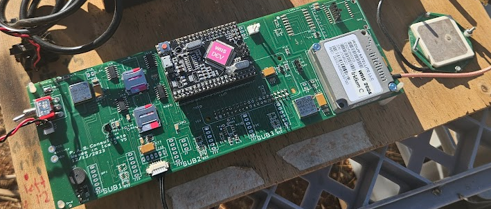
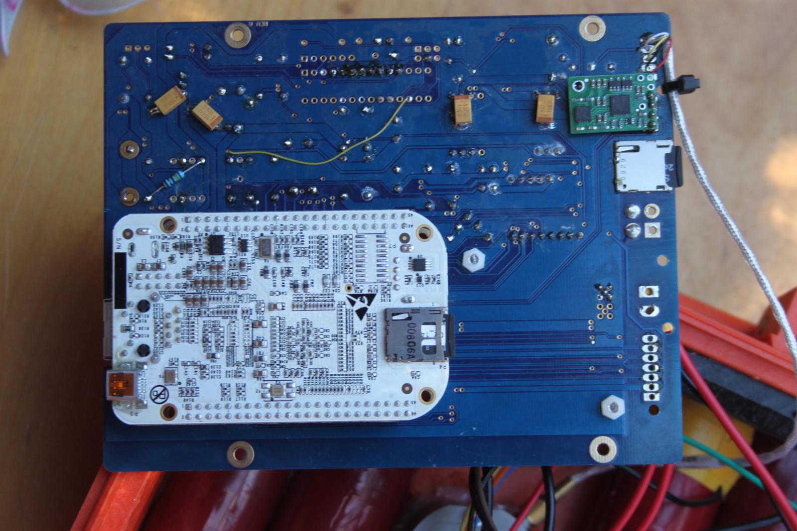
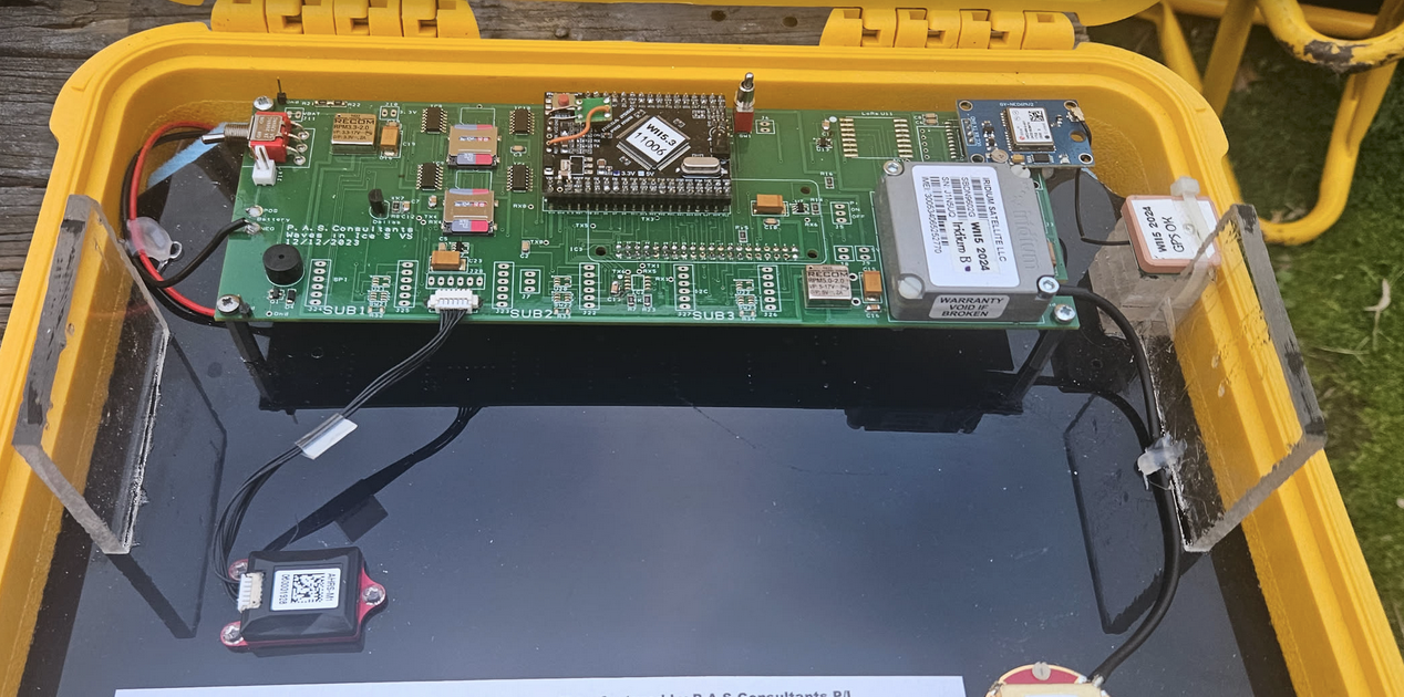
Main board, schematics (PDF), PCB designs, parts lists, and build photos.
The main board contains most of the electrical hardware on the basic model.
Electronic schematics (PDF)
PCB schematics
Parts list and references
Build instructions
Photos of finished boards
Status: pending public release. Sanitised schematics and BOM to follow.
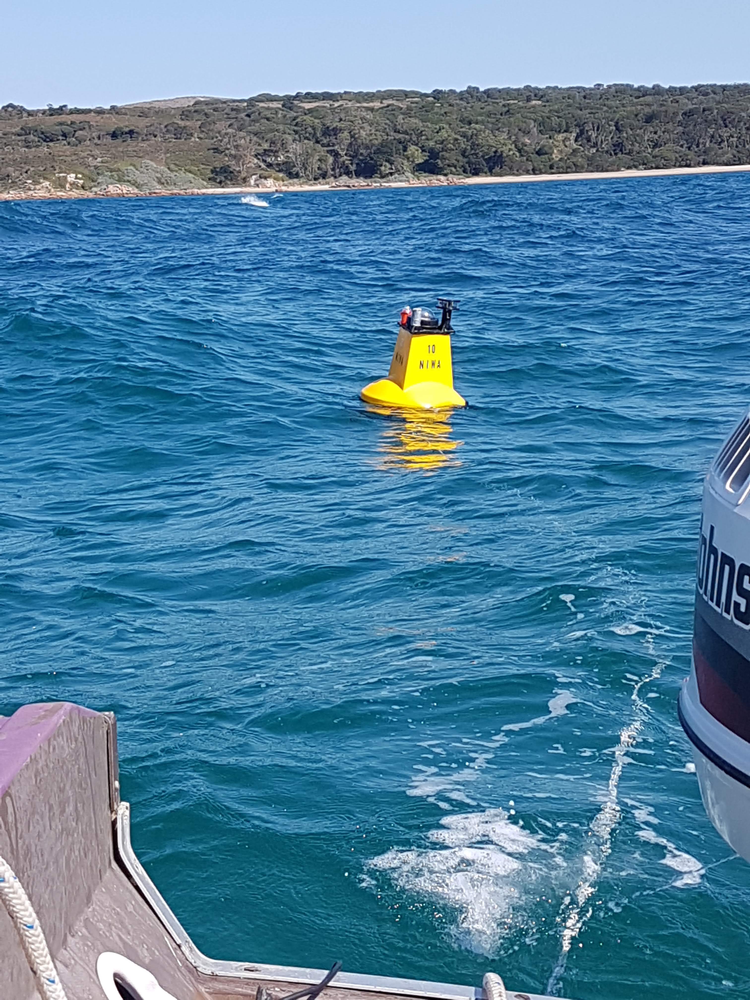
3 - Buoy Types
WII1 through WII5 — the lineage of WII wave buoys, their sub-types, and the photos and history of each.
The WII project has gone through five major buoy generations. Earlier units
were research prototypes; WII4 (Intel Edison-based) and WII5 (AVR/ESP32-based)
have multiple production sub-types covering different deployment profiles.
WII5 — current AVR/ESP32 generation, with sub-types.
3.1 - WII1 to WII3
First three generations of WII buoys — early research prototypes that laid the groundwork for the production WII4 (Edison) and WII5 (AVR) designs.
The first three WII generations were research prototypes — single-build
or small-batch units that proved out the sensors, communications, and
deployment patterns later productised in WII4 and WII5.
WII1 — the original 2012 AVR-based buoy. Modular firmware
(ADC, GPS, IMU, SD, temperature) running on a custom MegaPro 3.3 V
board.
WII2 — 2014 Scott Base build. Added the MPU9150 IMU, Kistler
high-precision accelerometer, and Iridium SBD telemetry at 2–8 Hz.
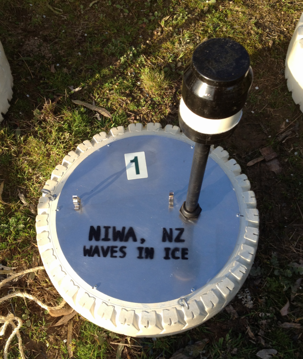
WII3 — successor with the WatchDog AVR + Linux dashboard
architecture, deployed at French Island, Port Phillip, and NIWA test
sites through 2016–17.
Status: placeholder. Per-generation history, photos, and deployment
notes to follow.
The WII4 generation used the Intel Edison module as its main CPU, running
Linux with a mix of C, shell, and Node code. Multiple sub-type variants were
produced over its run.
Sub-type A — placeholder name; rename when the variant is identified.
Sub-type B — placeholder name; rename when the variant is identified.
3.2.1 - WII4 Sub-type A
Placeholder WII4 variant — rename when the variant is identified.
Placeholder for one of the WII4 variants. Photos, deployment notes, and any
variant-specific differences from the main WII4 design go here.
3.2.2 - WII4 Sub-type B
Placeholder WII4 variant — rename when the variant is identified.
Placeholder for another WII4 variant.
3.3 - WII5
Current-generation WII5 buoy — AVR/ESP32 main board, multiple sub-type variants.
The WII5 generation is the current production design: AVR/ESP32 main board
running the C++ control firmware, with multiple sub-type variants for
different deployment profiles.
Sub-type A — placeholder name; rename when the variant is identified.
Sub-type B — placeholder name; rename when the variant is identified.
3.3.1 - WII5 Sub-type A
Placeholder WII5 variant — rename when the variant is identified.
Placeholder for one of the WII5 variants. Photos, deployment notes, and any
variant-specific differences from the main WII5 design go here.
3.3.2 - WII5 Sub-type B
Placeholder WII5 variant — rename when the variant is identified.
Placeholder for another WII5 variant.
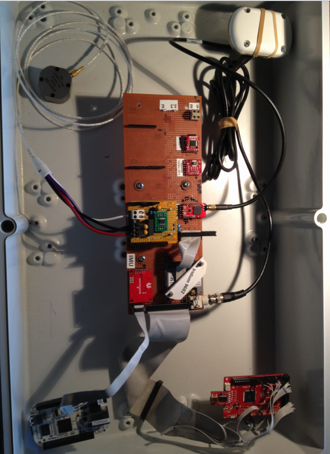
4 - Enclosures
Buoy enclosures — design decisions around ice, temperature, weight, anti-slide spikes, and survival in Antarctic deployment.
Enclosure designs for WII buoys, from the simplest ice-surface case through
fully floating buoys built to survive Antarctic deployment. Choice of
enclosure drives almost everything downstream — battery sizing, sensor
mounting, what the antenna can see, and how the buoy behaves when the ice
moves.
Design decisions
Ice survival
The enclosure has to live on or in sea ice for months. That means surviving
freeze-in, freeze-thaw cycles, ice ridging, and the mechanical loads when
floes collide. Critical points:
Sealing under thermal cycling. Gaskets that work at 20 °C can fail
below −30 °C. We use materials chosen for low-temperature flexibility and
test the full assembly through cold-soak cycles before deployment.
No external moving parts. Anything that hinges, slides, or rotates
will eventually freeze open or shut.
Drainage and ice expulsion. Water that gets in (and it always does)
must be able to leave before it freezes and cracks the housing.
Temperature range
WII buoys deploy from Antarctic winter (−40 °C ambient, colder with
wind-chill) through to direct-sun loading on dark surfaces in spring
(+30 °C internal). The electronics, battery, and seals all need to span
that. Practical consequences:
Battery chemistry has to keep delivering current at the cold end —
see battery notes per variant.
Internal heating from electronics is a feature, not a bug: it keeps
the package above the battery’s no-go floor when the buoy is awake.
Condensation on warm-up is managed with desiccant and by minimising
air volume inside the enclosure.
Weight
Weight matters at three different points in the buoy’s life:
Deployment — buoys are hand-deployed from ships, hovercraft, or
helicopters. Two-person lifting limits set an upper bound.
On-ice behaviour — too light and the buoy blows around in wind; too
heavy and it sinks slush or punches through thin ice.
Shipping — multiplied across 14-buoy deployments, every kilogram
shows in air-freight costs and field-camp logistics.
Anti-slide spikes
Buoys deployed on the ice surface need to stay where they’re put.
Smooth-bottomed enclosures will slide on tilted floes or melt-water pools
and end up far from the intended array geometry — or worse, slide into the
sea before retrieval.
Spikes on the underside dig into the surface ice and lock the
position.
Spike pattern is chosen to grip without penetrating so deep the buoy
becomes hard to retrieve when the surface refreezes around it.
Spike material has to match the ice/temperature regime — steel for
hard ice, harder alloys for ridged floes.
Antenna and visibility
The Iridium and GPS antennas need a clear view of the sky. The enclosure
top must be radio-transparent or carry an external antenna. Anti-slide
spikes and other surface features are arranged so they don’t shadow the
antenna or accumulate snow that would.
Variants
Variants range from:
A simple ice-surface box with spikes underneath
Floating buoys with weighted keels for sea-ice-edge deployment
Tethered designs that ride out specific deployment geometries
Status: placeholder. Mechanical drawings, photos, and CAD files to follow.
5 - Test Equipment
Test rigs and field tools — static wave/heave tester, off-grid access points, and local dashboards for watching real-time sensor data during testing.
The supporting equipment used to bring up, verify, and debug buoys —
either on the bench or out in the field where there’s no internet.
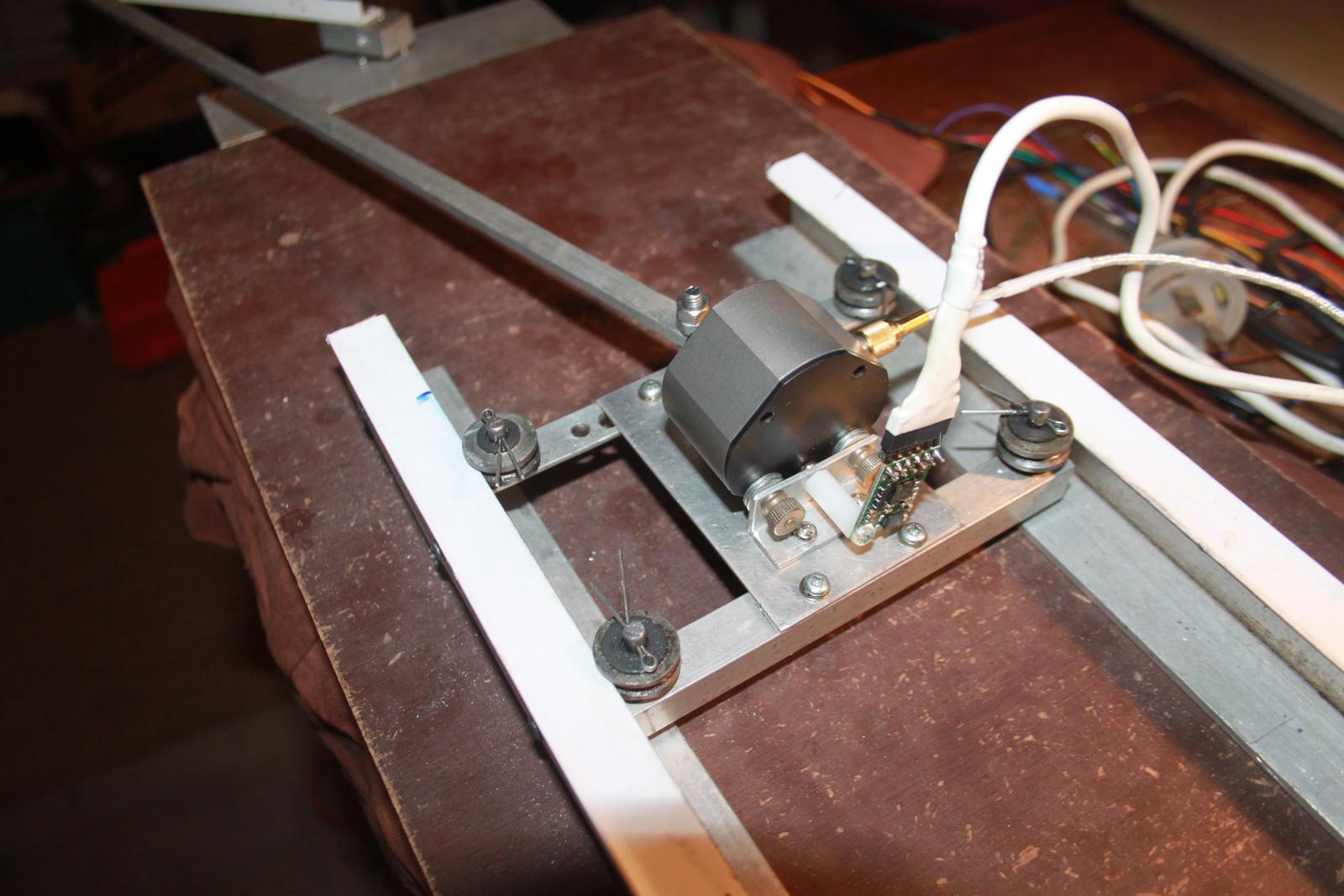
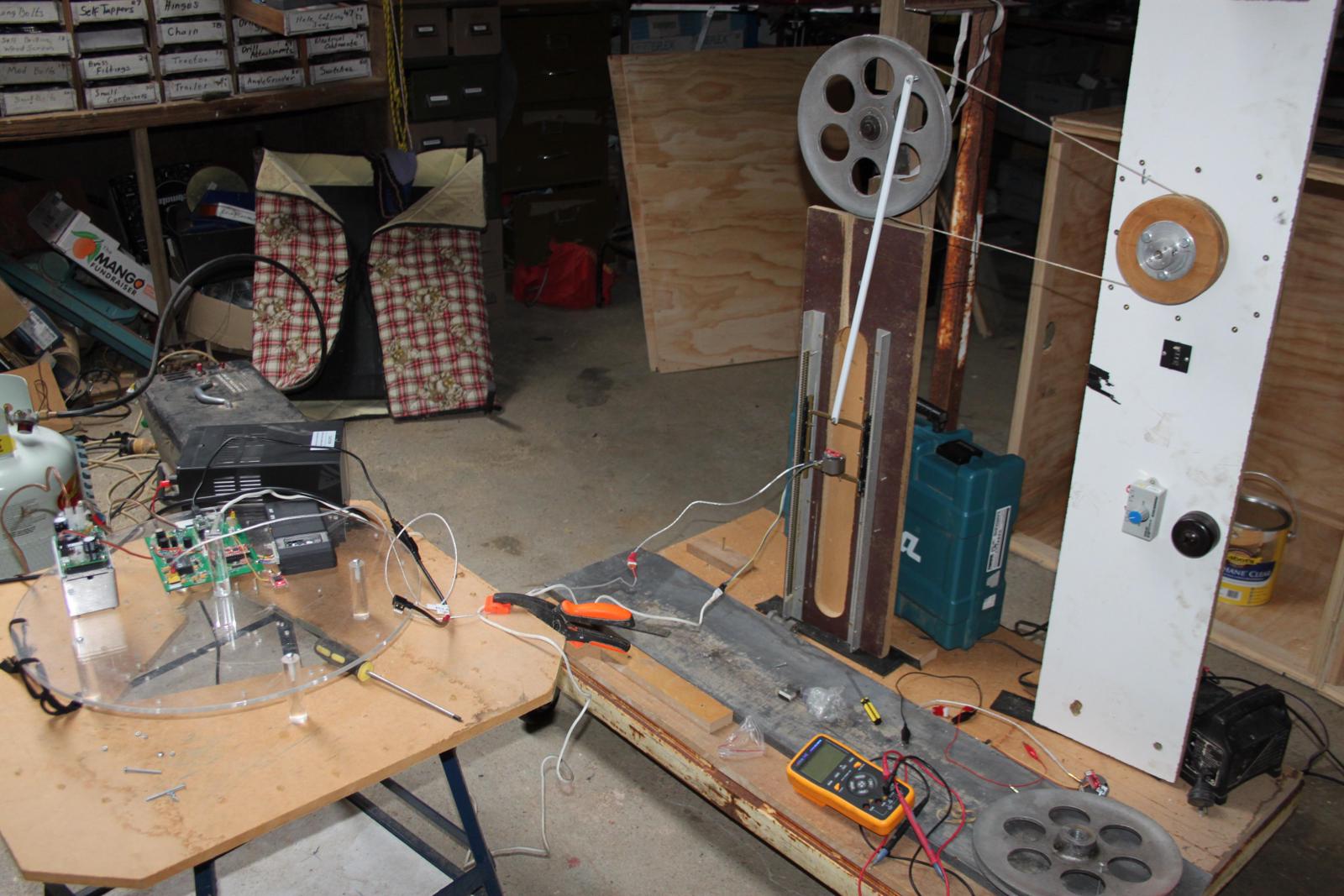
Static Wave/Heave Tester
A bench rig that imposes a known vertical motion on a buoy so its
accelerometer + maths pipeline can be calibrated and verified against a
ground truth. Used to:
Confirm the buoy reports the heave amplitude and period it actually sees
Catch sensor mounting errors before deployment
Regression-test firmware and maths changes against repeatable inputs
Status: placeholder. Mechanical design, drive method, and example test
traces to follow.
Off-grid Access Point
A portable Wi-Fi access point used in the field — at a remote test site,
on a ship, or anywhere there’s no internet. Lets the operator talk to
buoys, the maths Pi, and the local dashboards without needing
infrastructure to be there. Battery- or solar-powered, configured to work
with the buoy’s own Wi-Fi mode.
Status: placeholder. Hardware list, configuration, and field setup notes
to follow.
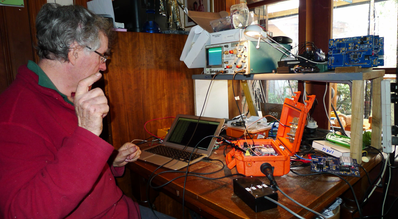
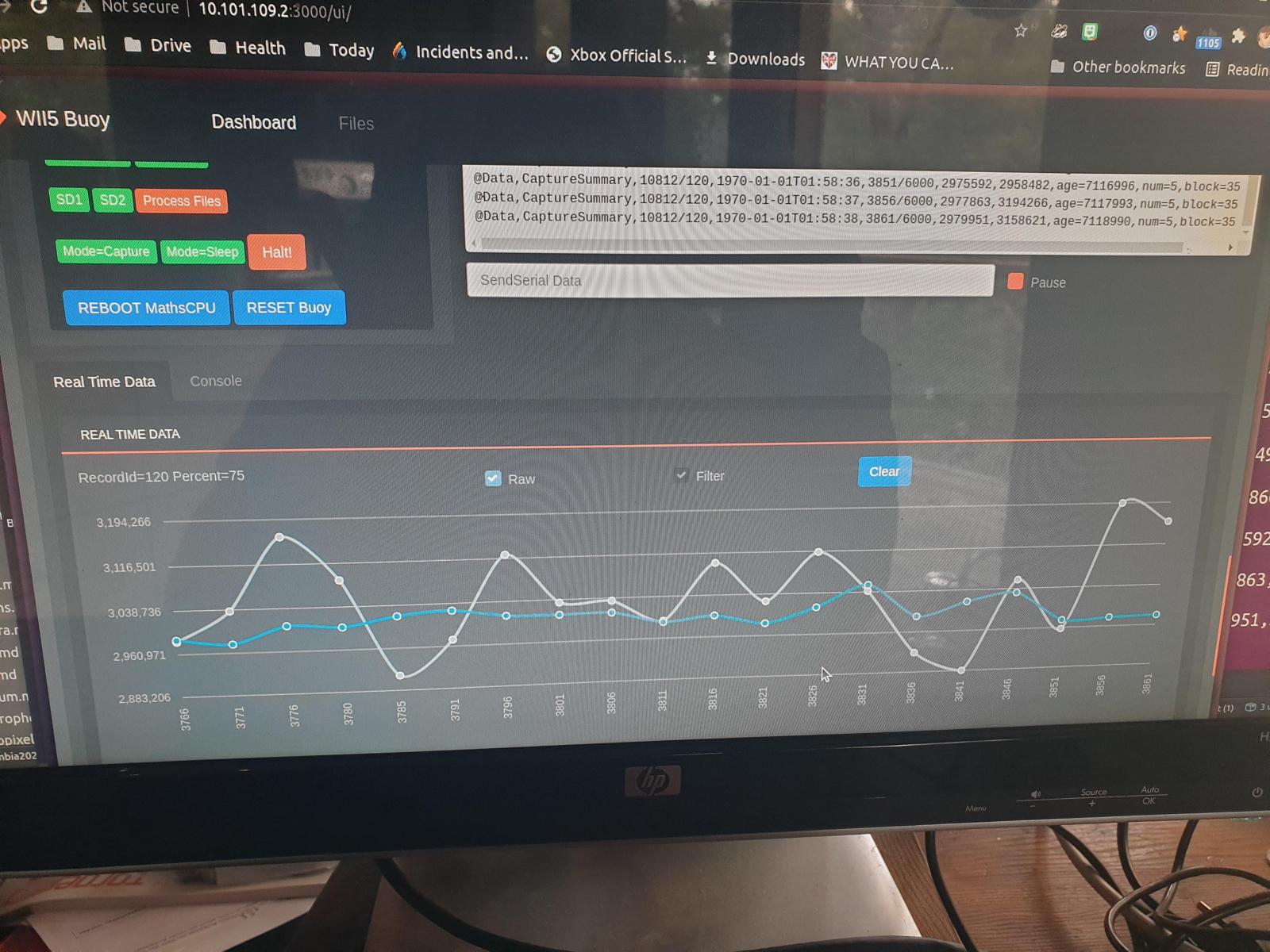
Local Dashboards
Web-based dashboards that run on the operator’s laptop or on the maths Pi
and show real-time sensor data during testing — accelerometer traces,
GPS lock state, battery voltage, temperature, IMU heading. The point is to
see what the buoy is doing while you’re holding it, before sealing it up
and trusting it to a deployment.
Status: placeholder. Screenshots and the local-server setup to follow.
BLE / Wi-Fi Access Boxes
Field tools used to configure and read out buoys without breaking the
enclosure seal: BLE access boxes, Wi-Fi access boxes, and the host-side
software that talks to them.
Status: placeholder. Tool designs and software to follow.
6 - Onboard Data Processing
The on-buoy maths is documented under Software → Onboard Data Processing. This page is a sidebar pointer.
The on-buoy maths — Alison Kohout’s wave-motion algorithms running on the
Maths CPU to reduce raw acceleration into a wave-statistics payload — is
documented under
Software → Onboard Data Processing.
This entry exists here so the Buoys sidebar has a pointer to it, because
the processing runs on the buoy even though the code lives in the
Software section.